EXTRUSION PROCESSES Extrusion Design Impact Extrusion Hydrostatic Extrusion MANUFACTURING PROCESSES Metal Casting Metal Forming Metal Rolling Metal Forging Metal Drawing Sheet Metal Powder Processes
Metal Extrusion
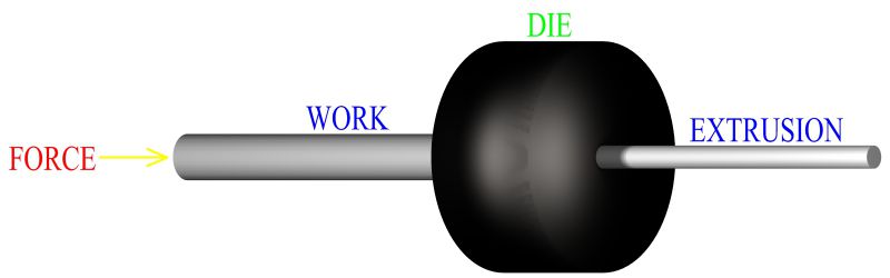
Metal extrusion is a metal forming process in which a work piece, of a certain length and cross section, is forced to flow through a die of a smaller cross sectional area, thus forming the work to the new cross section. The length of the extruded part will vary, dependant upon the amount of material in the work piece and the profile extruded. Numerous cross sections are manufactured by this method. The cross section produced will be uniform over the entire length of the metal extrusion. Starting work is usually a round billet, which may be formed into a round part of smaller diameter, a hollow tube, or some other profile. The basic principle of metal extrusion is illustrated in figure 208.
Figure:208
|
In this case, a round billet is forced through a die opening creating a round part of reduced diameter. The ram will continue to move forward, pushing more of the billet material through the die opening. As this occurs, a continuous length of work will emerge from the other side of the mold at a certain velocity relative to the speed of the ram. When manufacturing an extruded product, considerations to support and guide the length of material as it exits the die are important. As the ram reaches the end of its stroke, a small portion of the billet stock can not be pushed through the die opening. This last part of the work metal is called the butt end. The product is cut at the die opening to remove it from the butt end material. In manufacturing industry, methods have been developed to extrude a wide variety of different materials. Some materials are better suited for extrusion manufacture than others. Aluminum is an extremely good material for metal extrusion. Copper, magnesium, zinc, tin and some softer low carbon steels, can also be extruded with little complication due to the material. High carbon steels, titanium and various refractory alloys, can be difficult to extrude.
Extrusion is capable of creating tremendous amounts of geometric change and deformation of the work piece, more than other metal forming processes. Metal extrusion tends to produce an elongated grain structure, usually considered favorable, in the part's material in the direction that the work is extruded. Extrusion, in many instances, can be considered a semi continuous manufacturing operation. Continuous because the process will manufacture a continuous length of the same cross section. From this length, individual discrete parts can be cut. It is semi continuous and not completely continuous, (such as continuous casting), because the length of extruded product is still limited by the amount of material in the work piece. The work piece must be reloaded at the end of every cycle. Metal extrusion can also be a discrete manufacturing process, producing a single part with every cycle. As in other metal forming operations, the forces involved and the material flow patterns that occur during extrusion are of primary concern in the analysis and development of this manufacturing process. The many factors that affect metal flow will be discussed.
Cold Extrusion Or Hot Extrusion
Metal extrusion is a forming process, like other metal forming processes, it can be performed either hot or cold. The characteristics of hot forming and cold forming were discussed in detail in the fundamentals of metal forming section.
Hot forming, or hot working, involves working a metal above its recrystallization temperature. Hot working has many advantages in the improvement of the mechanical properties of the part's material. Cast metal contains pores and vacancies throughout the material. Hot working will push and redistribute material, closing up these vacancies. Impurities in molten metal usually combine together in masses upon hardening, forming solid inclusions within the metal. These inclusions cause weakness in the surrounding material. Hot working causes these inclusions to break up and distributes them throughout the mass of metal. Large, irregular, columnar grain structures are usually present in cast parts. Hot working a metal will break up irregular structures and recrystallize the mass of material into a finer wrought grain structure. Mechanical properties of the part, such as impact resistance, ductility and strength characteristics, are improved. If a hot extrusion is performed on a cast work piece, then the advantages of hot working will be imparted to the work. However, most metal extrusions in manufacturing industry are performed on billets that have already been hot formed, thus the mechanical advantages of hot forming have already been imparted to the material.
In addition to the improved physical characteristics of the metal, hot working does offer other advantages in a manufacturing process. A metal above its recrystallization temperature is more easily manipulated than a cold metal. An increase in temperature results in a corresponding decrease in strength and an increase in ductility, factors more advantageous in the forming of the metal.
When metals are worked above their recrystallization temperature strain hardening does not occur, thus hot working allows for a large amount of shape change. One of the major disadvantages of hot working of metals is the oxidation that occurs over the surface of the hot work. This results in a layer of oxide scale build up on the external surfaces of the work piece. Scale can affect surface finish and accuracy of the part as well as increasing friction and wear at die metal interfaces. Heating to, and maintenance of, high working temperatures, decreased tolerances, and increased die wear, are all disadvantages of a hot forming manufacturing process over a cold one.
Choosing between hot extrusion or cold extrusion will depend on the specific details of the manufacturing process. Some of the more difficult to form materials may have to be worked hot. Some easy to extrude metals, such as aluminum, can be worked either hot or cold depending upon other factors in the process. Hot extrusion of metal is generally preferred for larger parts, more extreme changes in shape and extrusions with more complex geometry. Cold extrusion of metal is usually used for smaller parts, less complex shapes, more workable materials and the manufacture of discrete extrusions that create a single part with each operation. Impact extrusion, a discrete manufacturing process, is most often performed cold.
Advantages of cold extrusion over hot extrusion include, not having to heat the work, higher production rate, no oxidation and scale form on surfaces, greater geometric accuracy, better surface finish and the ability to strengthen the part by way of strain hardening. In hot extrusion, like other hot forming processes, the heat transfer between the work piece and the cooler surfaces of the die presents a problem during the manufacturing operation. In order to mitigate this issue, die used for extruding can be preheated to lessen the temperature gradient. Lubricants also help in the reduction of heat transfer between the part and the mold. With some particularly difficult to extrude materials isothermal extrusion may be employed, this is similar in concept to isothermal forging. In these instances, the mold is maintained at, or slightly below, the temperature of the work during the entire process.
Direct Extrusion Compared With Indirect Extrusion
Metal extrusion processes, in manufacturing industry, can be classified into two main categories, direct and indirect. Hollow extrusions, as well as cross sections, can be manufactured by both methods. Each method, however, differs in its application of force and is subject to different operational factors.
Direct Extrusion
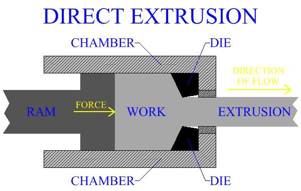
Direct extrusion is a similar metal extrusion process to the one illustrated in figure 208. In direct, or forward extrusion, the work billet is contained in a chamber. The ram exerts force on one side of the work piece, while the forming die, through which the material is extruded, is located on the opposite side of the chamber. The length of extruded metal product flows in the same direction that the force is applied.
Figure:209
|
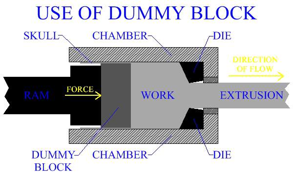
During direct extrusion, metal flow and forces required are affected by the friction between the work piece and the chamber walls. Particularly in hot working, oxide scale build up on the outer surfaces of the work piece can negatively influence the operation. For these reasons, it is common manufacturing practice to place a dummy block ahead of the ram. The dummy block is of slightly smaller diameter than the chamber and work piece. As the metal extrusion proceeds, the outermost surface of the work is not extruded and remains in the chamber. This material will form a thin shell, (called skull), that will latter be removed. Much of the skull will be comprised of the surface layer of oxidized scale from the work metal.
Figure:210
|
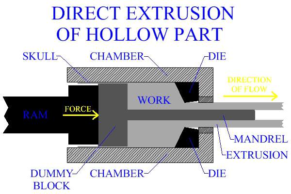
Hollow, or semi hollow, parts can be directly extruded with the use of a mandrel attached to the dummy block. A hole is created through the work, parallel to the axis over which the ram applies the force to form the extrusion. The mandrel is fitted within this hole. Once the operation begins, the ram is forced forward. The extruded metal flows between the mandrel and the die surfaces, forming the part. The interior profile of the metal extrusion is formed by the mandrel, while the exterior profile is formed by the extruding die.
Figure:211
|
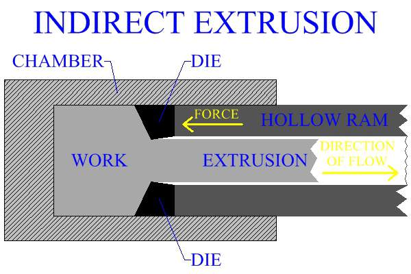
Indirect Extrusion
Indirect extrusion is a particular type of metal extrusion process in which the work piece is located in a chamber that is completely closed off at one side. The metal extrusion die are located on the ram, which exerts force from the open end of the chamber. As the manufacturing process proceeds, the extruded product flows in the opposite direction that the ram is moving. For this purpose the ram is made hollow, so that the extruded section travels through the ram itself. This manufacturing process is advantageous in that there are no frictional forces between the work piece and the chamber walls. Indirect extrusion does present limitations. Tooling and machine set up are more complicated, hollow rams are not as strong and less ridged and support of the length of the metal extrusion's profile, as it travels out of the mold, is more difficult.
Figure:212
|
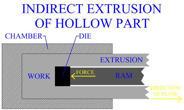
Indirect extrusion can also be used to produce hollow parts. In this process, a ram is forced into the work material. The ram gives the internal geometry to the tubular part, while the material is formed around it. Difficulties in supporting the ram limit this process and the length of tubular metal extrusions that may be manufactured.
Figure:213
|
Metal Extrusion Practice For Manufacturing
Metal extrusion practice, in manufacturing industry, must take into consideration a variety of factors, many of which will be specific to each particular operation. The type of material, size of work piece, geometric cross section of extruded part, ram speed, temperature of work and type of metal extrusion process, are all important elements in the design and analysis of an extrusion operation. The main goal is to enact the right metal flow through the correct application of force. The force is applied through a ram, powered by some sort of press. Most extrusions are performed horizontally, by hydraulic presses. Hydraulic presses can deliver a constant force, at a constant speed, over a long stroke, making them ideal for extruding metal parts; however, in some instances mechanical presses may be used. The ram's speed affects the forces involved during the operation. Ram speeds can be as low as a few feet every minute, or may be as high as 15 feet per second, though most are under 2 feet per second. The length of extruded metal product in common manufacturing practice is generally up to 25 feet, but much longer lengths, as high as 90 feet, have been created. Many of the extruded sections produced in industry require bending or straightening after the completion of the extrusion process. When performed correctly, metal extrusion can be very economical for both small and large batch production.
Metal Flow During Extrusion
During a metal extrusion process, metal from a work piece of a certain cross section is forced to flow through a die of smaller cross section, forming an extruded part. It is important to understand the flow of material that occurs as the part is being formed. In some ways it is similar to fluid flowing from one channel into another channel of decreasing width. The metal is deformed and forced to flow together as it progresses towards, and through, the die. As the work travels through the die, the outer layers are deformed more than the ones closer to the middle. The outer sections, further from the central axis, will experience greater material displacement and will have more turbulent metal flow characteristics. The material closer to the center will move faster through the mold, meaning it will have the higher velocity relative to the die. With square die, which are die with 90 degree angles, sections in the material close to the mold opening, but adjacent to the die, may not move. These areas, termed dead zones or dead metal zones, are indicative by stagnation of metal flow. Note that there will be a type of shearing of the material occurring between layers, at the interfaces of dead zones.
Extrusion Ratio
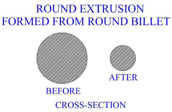
The extrusion process is capable of creating a tremendous amount of metal deformation of the work. The size of the cross section of the work billet may be much larger than the size of the cross section of the extruded part. For example, in figure 214 the starting work billet has a certain diameter, say 10 inches. It is formed into a round extrusion with a diameter of 5 inches. We can relate the size of the work's cross section with that of the extruded part by comparing their diameters. It can be said that the extrusion has a diameter of 1/2 the original work, thus measuring the cross sectional reduction that occurred during the metal manufacturing process.
Figure:214
|
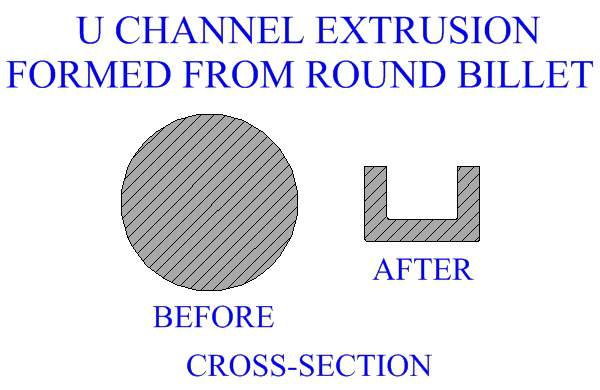
This is an easy relationship to make, since both the work and the metal extrusion are round. If the work and the extruded part have a different profile, another means will be needed to relate their sizes. For example, in figure 215 a round billet is extruded into a smaller u-channel profile.
Figure:215
|
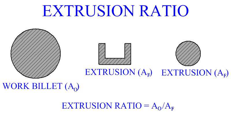
To relate the cross section of the work piece to that of the extruded product, the extrusion ratio was established. The extrusion ratio is the ratio of the area of the work's cross section (Ao) to that of the extrusion's cross section (Af). The extrusion ratio, or reduction ratio, can be expressed as (Ao/Af).
Figure:216
|
Obviously, since the starting work's cross section will be greater than that of the metal extrusion, the extrusion ratio will always be more than 1. In manufacturing industry, extrusion ratios typically range from about 4 to 100, although they can be even higher in certain special cases.
Extrusion Shape Factor
The exact geometric profile of a metal extrusion's cross section will have an effect on the force required to extrude the work. A completely round circle cross section requires the least amount of work to extrude. Generally the more complex a shape, the more force that will be needed to extrude a cross section of that shape. In order to quantify the effect that different cross sectional profiles have on metal extrusion force requirements, the extrusion shape factor was established. The lower the shape factor, the lower the relative pressure needed to extrude that cross section. A completely round circle profile has a shape factor of 1, the shape factor increases as the part becomes more complex. The actual shape factor calculation is relative to the ratio between the perimeter of the extruded cross section and the perimeter of a circle of the same area.
Circumscribing Circle Diameter
As noted, the geometry of an extruded metal profile is a large factor in force requirements for that manufacturing operation. As in all processes, there are always limitations on the size of parts that may be manufactured based on the physical natures of the process. The work material is an important characteristic in determining the size limitations for an extruded part. Stronger materials require more pressure to form, therefore the maximum size of an extrusion will be lower for more difficult to shape metals.
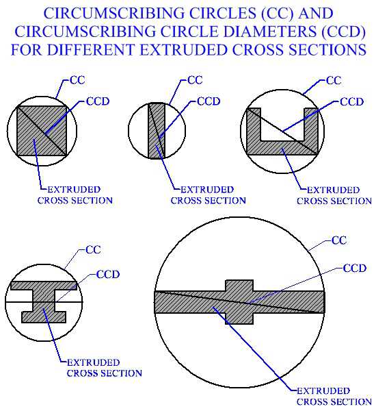
Another method, used in manufacturing industry, to quantify the geometry of a metal extrusion's profile, particularly with regard to size, is the circumscribing circle diameter. The circumscribing circle diameter is simply the diameter of the smallest circle that the profile of the extruded cross section can fit. Aluminum is one of the easiest to shape metals for extrusion. The range of circumscribing circle diameters for extruded aluminum parts, for industrial manufacturing production, typically spans from 1/4 inch to 10 inches. Although much larger aluminum parts have been extruded in certain operations. Figure 217 shows some different cross sectional profiles produced by metal extrusion, with their circumscribing circles and circumscribing circle diameters.
Figure:217
|
Metal Extrusion Die
Metal extrusion die, used in manufacturing extruded sections, must have certain mechanical characteristics. Extrusion die must be strong and hard, capable of holding their dimensional accuracy throughout the high stresses created during the manufacturing process. They must also be resistant to wear, which is always an issue when extruding metal in large quantities. Dies for hot extrusion must have high thermal resistance and be able to maintain strength and hardness at elevated temperatures. Tool steels are a common type of material for metal extrusion molds. Extruding dies may be coated to increase wear resistance. Carbides are sometimes used for a mold material, carbides do not wear easy and can provide accurate part dimensions.
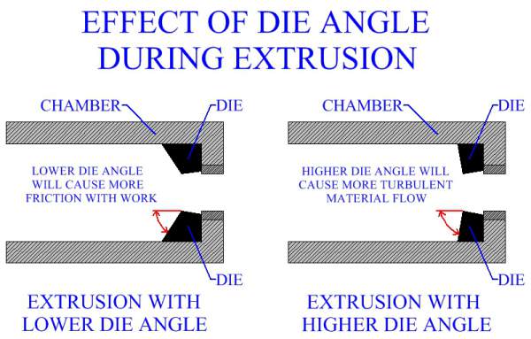
Extrusion die angle is an important factor in the manufacturing process, as it is a large determinant in the flow of material. The amount of force necessary to form a certain cross section will vary with different die angles. A lower angle will create more friction at the work-die interface. Friction is a factor that increases the force necessary to extrude a part. High die angles create more material movement, particularly in the outer regions away from the center. The greater metal displacement gives a greater turbulence in the metal flow. Increased turbulence in the flow also increases the amount of force necessary for the operation. All factors must be calculated in the design of a metal extrusion process.
Figure:218
|
The optimum die angle will balance out the more extreme friction of lower die angles with the more extreme turbulence of higher die angles, and be somewhere between the two extremes. The exact optimum die angle is difficult to determine for any metal extrusion process due to the influence of other operational factors, such as temperature and lubrication. The manufacturing engineer must try to provide the best angle based on all the considerations of a given operation.
Lubrication
Lubrication is used, in manufacturing industry, to assist in metal flow over the work-mold surfaces as a part is being extruded. Soaps, oils, graphite immersed in oil and many other special lubricants are all used in manufacturing industry to extrude parts. Some materials can be problematic in that they tend to stick to the tooling. To prevent sticking, a softer metal may be used for lubrication. In this case, the softer metal will be jacketed around the work. For manufacturing practice, particularly in high temperature processes, molten glass is often employed as an effective lubricant in the extrusion of tougher materials.